
UART on the MachXO3 Starter Kit
Published:
The MachXO3 starter kit is a handy little field programmable gate array (FPGA) board that can be found for around $55. While working with the starter kit, I found myself wanting to communicate data between the FPGA and a computer. This is accomplished on other development boards, such as the Arty S7, by providing a USB to UART bridge for this communication along side the USB to JTAG programming circuitry. While the MachXO3 starter kit does provide USB to JTAG programming, it does not support USB to UART out of the box.
The MachXO3 starter kit has an FTDI FT2232HL chip which supports conversion of USB to dual channel JTAG, UART, and some other protocols. As such, I decided to dive into the schematics Lattice Semiconductor handily provide in their user guide.
So, lets dig in!
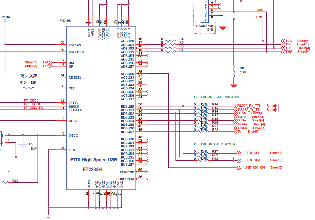 Capture from page 21 of the MachXO3 starter kit user guide.1
This part of the schematic, found on page 21 of the user guide, shows that connections to port B of the FTDI chip and the rest of the board go through a set of resistors that are marked as DNI or do not install. We’ll store away the resistor identifiers R14 and R15 for later. The traces we care about for UART data transmission from the FTDI chip are labeled as RS232_Rx_TTL and RS232_Tx_TTL and marked as being connected on page 4 of the schematic, so let’s pop over to that page to see where they end up.
Capture from page 23 of the MachXO3 starter kit user guide.1
Now we can see the traces for RS232_Rx_TTL and RS232_Tx_TTL connect to pin A11 and C11 of the FPGA package. Therefore, we can get USB to UART communication as long as traces physically exist on the starter kit board and we can short the pads of R14 and R15. While the traces labeled FTDI_SCL and FTDI_SDA connect to the FTDI chip in the same place as RS232_Rx_TTL and RS232_Tx_TT, these traces terminate at test points on the PCB.
Now to get USB to UART communication working
| 
|
|---|---|
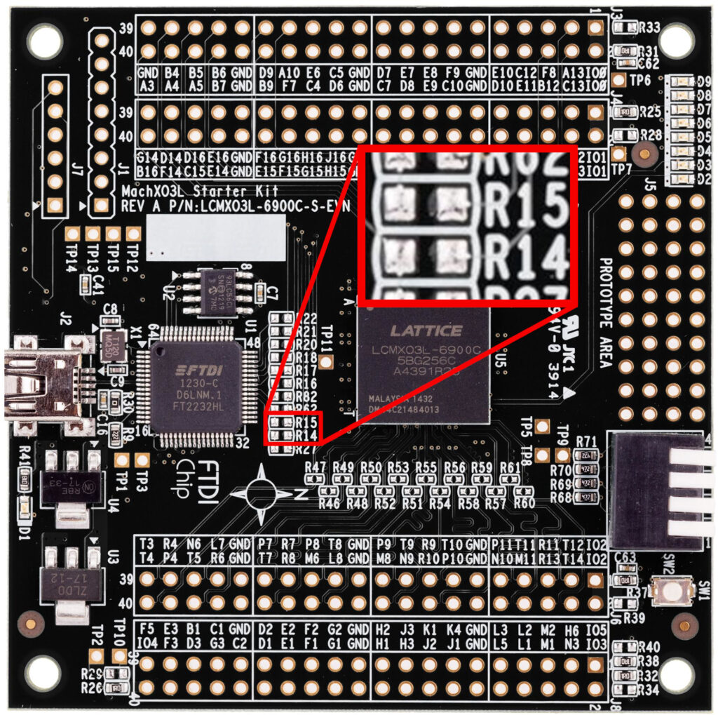
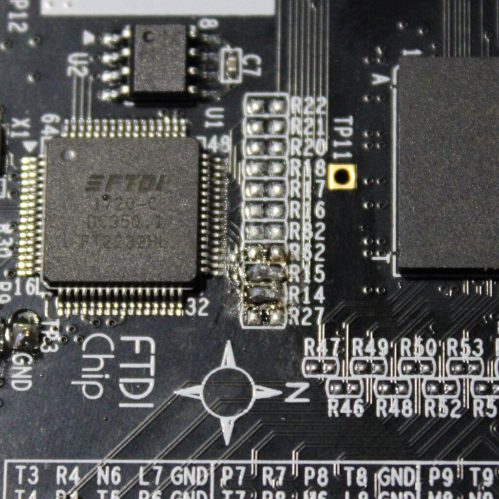
| Location of R14 and R15.2 | R14 and R15 pads bridged by solder. |
The first step is to bridge the R14 pads and R15 pads which are located right next to the FTDI chip. This covers the hardware changes that need to be made, but we need to set up the FTDI chip to operate in UART mode on port B. To perform this change, we need to use FTDI’s FT_Prog utility.
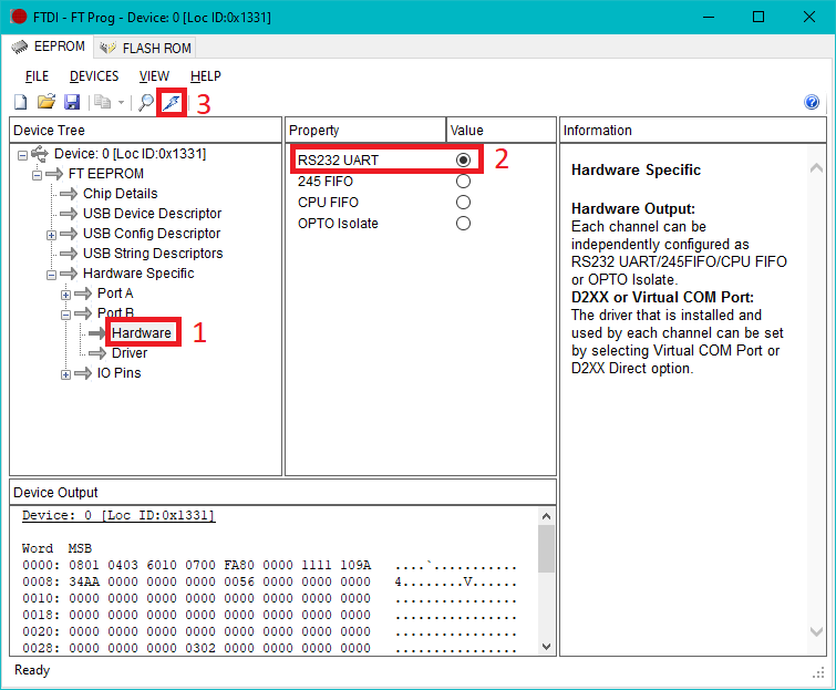
| 1. Inside of FT_Prog, we navigate to FT EEPROM -> Hardware Specific -> Port B -> Hardware while the starter kit is connected via USB 2. Then, select RS232 UART 3.The FTDI chip needs to be programed with this setting by clicking the lightning bolt |
Port B of the FTDI chip will now act as a USB to UART bridge. Communication can be established using the D2XX or virtual COM port drivers. You will need to program the FTDI chip to use the appropriate driver within FT_Prog which is found under FT EEPROM -> Hardware Specific -> Port B -> Driver. All that is left now is to either use the UART available in Lattice Diamond’s IPexpress or create your own and connect the design signals to A11 and C11 in the design constraints.